In #electric circuits, there are two types of systems. They are single-phase systems and three-phase systems. In single-phase systems, the current flows through a single wire and to complete the circuit there is a return path called a #neutral line. In single-phase systems, there is only one phase.
A three-phase system has three #phases. The three phases are sent together from the generator to the load. Each phase will have a phase difference of 120°. All the three phases in a three-phase system are involved in generating the #power so that the power is continuous.
Line voltage: The #voltage between two phases in three-phase circuits is termed line voltage.
Phase voltage: Phase voltage is the voltage between one phase and the neutral line.
Three-phase #sinusoidal waveforms are shown below.

Generation of three-phase voltage:
In three-phase circuits, there are three equal voltages or EMFs whose #frequency is the same but there is a phase difference of 120°. A three-phase AC #generator produces these three voltages. A three-phase AC generator has three identical #windings which are electrically 120° degrees apart.
Consider three coils RR', YY', and BB'. The angle between the windings is 120° as illustrated in the figure below.

When the coils are rotated with a uniform velocity of w radians per second, an #emf is induced in the coils that are displaced by 120°. Assuming the voltage to be sinusoidal, the instantaneous values of the voltages of the three phases can be written as
V(RR') = Vm sin(wt)
V(YY') = Vm sin(wt - 120°)
V(BB') = Vm sin(wt - 240°)
The algebraic sum of the three voltages at any instant must be zero.
Phase sequence:
The phase sequence is the sequence in which the 3 phase supply reaches the maximum positive value.
Generally, #RYB is the phase sequence.
Types of connections in three-phase systems
Three-phase systems can be connected in two ways. They are
Star connection
Delta connection
1. Star connection:
The following figure shows the star connection

In #star connection, four wires are used out of which three are phase wires and one is the neutral wire. The neutral wire is taken from the star point. As it has a neutral point it is preferred for power #transmission over long distances.
If the current in all three phases is equal, then the current is said to be a balanced current. If the current in any one of the phases is different then it is said to be an unbalanced current. The neutral line does not have a significant role in the case of balanced current but in the case of unbalanced current, it has a significant role. It protects the transformer by making the unbalanced current flow towards the ground.
Line voltage in star connection is √3 times the phase voltage. The current is the same for line and phase.
Delta connection:
The delta connection is shown below

In #delta connection, three wires are used which is there is no neutral line in delta connection. As there is no neutral line the effect of unbalanced current cannot be eliminated so these are preferred for short distances. The ground can be used if neutral is required in the load station.
The line and phase voltages are equal in delta connection. Line current is given by √3 times the phase current.
There are four different ways in which star and delta connections can be arranged. They are
Star-Star connection
Star-Delta connection
Delta-Star connection
Delta-Delta connection
Three-phase Transformer connections:
1. Star-Star connection:
The star-star connection of the three-phase transformer is shown in the figure below.

As shown in the above figure, in this connection both #primary and #secondary windings are connected in star. This type of connection is used for a small high voltage transformer as the phase voltage is (1/√3) times that of line voltage, the number of turns per phase, and it requires less quantity of insulation.
2. Star-Delta connection:
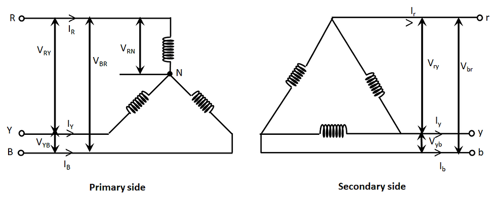
The Star-Delta connection of the three-phase transformer is shown below.

The primary of the transformer is connected in star connection and secondary is connected in delta connection. In this type of connection, there is a phase difference of 30° between primary and secondary line voltages. Large high voltage step-down transformers use this type of connection.
3. Delta-Star connection:
The Delta-Star connection of these phase transformers is shown in the following figure.

In this type of connection, the primary is connected in delta connection and the secondary is connected in star connection. On the secondary, as it is star connection neutral is available so it can be used for 3 phase, 4 wire supply system.
4. Delta-Delta Connection:
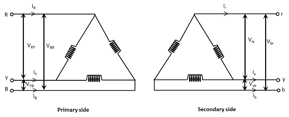
The Delta-Delta connection of the three-phase #Transformer is shown below.

In this type of connection, the primary and the secondary are connected in a delta connection.
Between primary and secondary there is no phase shift. It is used low voltage transformers.
See Also:
Follow us -
Please do follow us i.e #learnelectronicsindia to get daily updates about new blogs, videos, courses, quizzes, and contests.
Author -
Written By: Nagapuri Swathi


Clear and concise. LearnElectronics India's expertise shines through.
Learn Electronics India deserves a standing ovation for this comprehensive guide on three-phase circuits. The level of detail and clarity in the explanations is outstanding. I've been in the field for years, and this article still managed to teach me a few new things. Hats off to your team for creating such an enriching resource.